Project Type
Senior Design Capstone
Senior Design Capstone Project
An educational FPGA and embedded-systems platform developed to give engineering students hands-on experience with HDL design, AXI peripherals, simulation, hardware deployment, and system integration using the Digilent Cora Z7.
Project Type
Senior Design Capstone
Primary Purpose
Hands-on FPGA Education
Platform
Digilent Cora Z7
My Role
Project Manager and XSA Integration Owner
Overview
404: Bot Not Found was an eight-person senior design project centered on developing a reusable FPGA learning platform for Texas State University’s Digital Systems Using HDL course.
The platform was built around the Digilent Cora Z7, which combines Zynq-7000 programmable logic with an ARM processing system. This architecture allowed students to study HDL development, embedded programming, AXI communication, peripheral integration, simulation, and hardware verification in one environment.
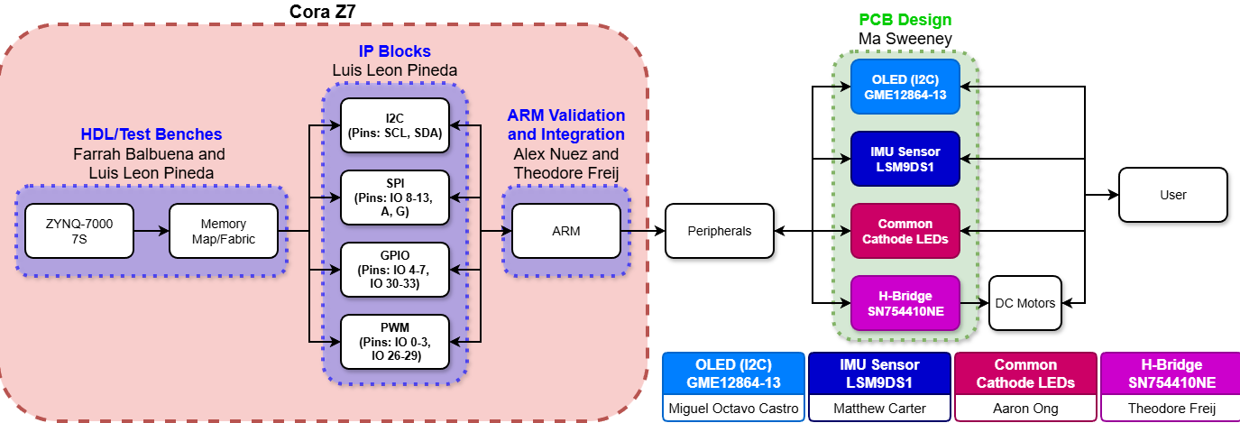
The system integrated GPIO, SPI, I2C, and PWM peripherals through an AXI-based architecture. These interfaces connected the Cora Z7 to external sensors, OLED displays, LEDs, motor-control hardware, and a custom peripheral PCB.
Testbenches, embedded applications, bitstream releases, hardware platforms, test procedures, and technical documentation were developed alongside the hardware so that future students could reproduce, study, and expand the system.
Educational Purpose
The project addressed the gap between learning HDL syntax in a classroom and developing a complete FPGA-based system. Students could follow a practical engineering workflow: create digital logic, simulate its behavior, integrate IP, build the design, deploy it to hardware, and verify the result.
The platform also demonstrated the relationship between software and programmable hardware. Embedded C applications running on the ARM processor accessed AXI-connected peripherals implemented in the FPGA fabric, allowing students to see how firmware and digital logic work together.
Instead of presenting the system only as a finished demonstration, the project provided reusable hardware, software, verification examples, and instructional documentation that could support future laboratory exercises.
System Architecture
The platform used the dual architecture of the Zynq-7000 SoC. The ARM processing system handled embedded software and high-level control, while the programmable logic contained AXI-connected peripheral interfaces and custom hardware.
AXI SmartConnect provided memory-mapped communication between the processing system and programmable-logic peripherals. The complete platform connected these interfaces to displays, sensors, LEDs, buttons, motor drivers, DC motors, and a custom PCB.
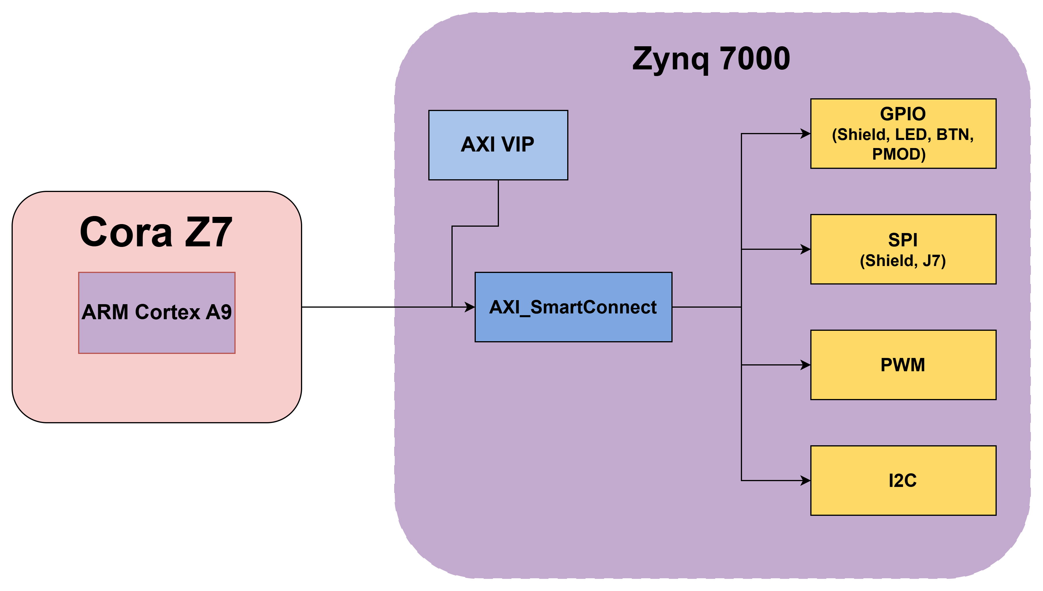
The ARM Cortex-A9 processing system ran embedded C applications, managed high-level control, and accessed peripherals through memory-mapped AXI interfaces.
The FPGA fabric contained AXI-connected GPIO, SPI, I2C, PWM, reset, interconnect, and custom hardware blocks.
External hardware included OLED displays, an inertial sensor, RGB LEDs, buttons, motor drivers, DC motors, and a custom peripheral PCB.
SystemVerilog testbenches and AXI VIP generated register transactions and verified peripheral behavior before hardware deployment.
FPGA Integration
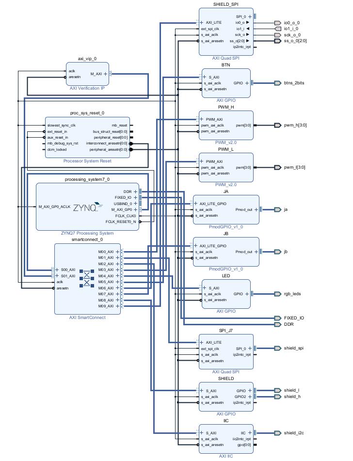
The Vivado block design brought together the Zynq processing system, AXI SmartConnect, processor resets, AXI Verification IP, GPIO interfaces, SPI controllers, an I2C controller, and custom PWM peripherals.
Each peripheral was assigned a memory address that allowed embedded software and testbench transactions to access its control and status registers. As the individual subsystem designs changed, the master hardware platform had to be updated and rebuilt while preserving clocking, reset behavior, address mapping, and external pin routing.
Project Deliverables
The completed project extended beyond a single FPGA design. It included the hardware platform, embedded applications, physical peripherals, simulation tools, deployment files, and instructional resources required to reproduce and understand the system.
A complete Zynq-7000 block design integrating the processing system, programmable logic, AXI interconnect, and peripheral IP.
Version-controlled FPGA deployment files that kept the hardware and embedded-software environments synchronized.
Testbenches and AXI VIP transactions for validating GPIO, SPI, I2C, and PWM register interfaces.
Embedded C examples for configuring peripherals and demonstrating communication between the ARM processor and FPGA fabric.
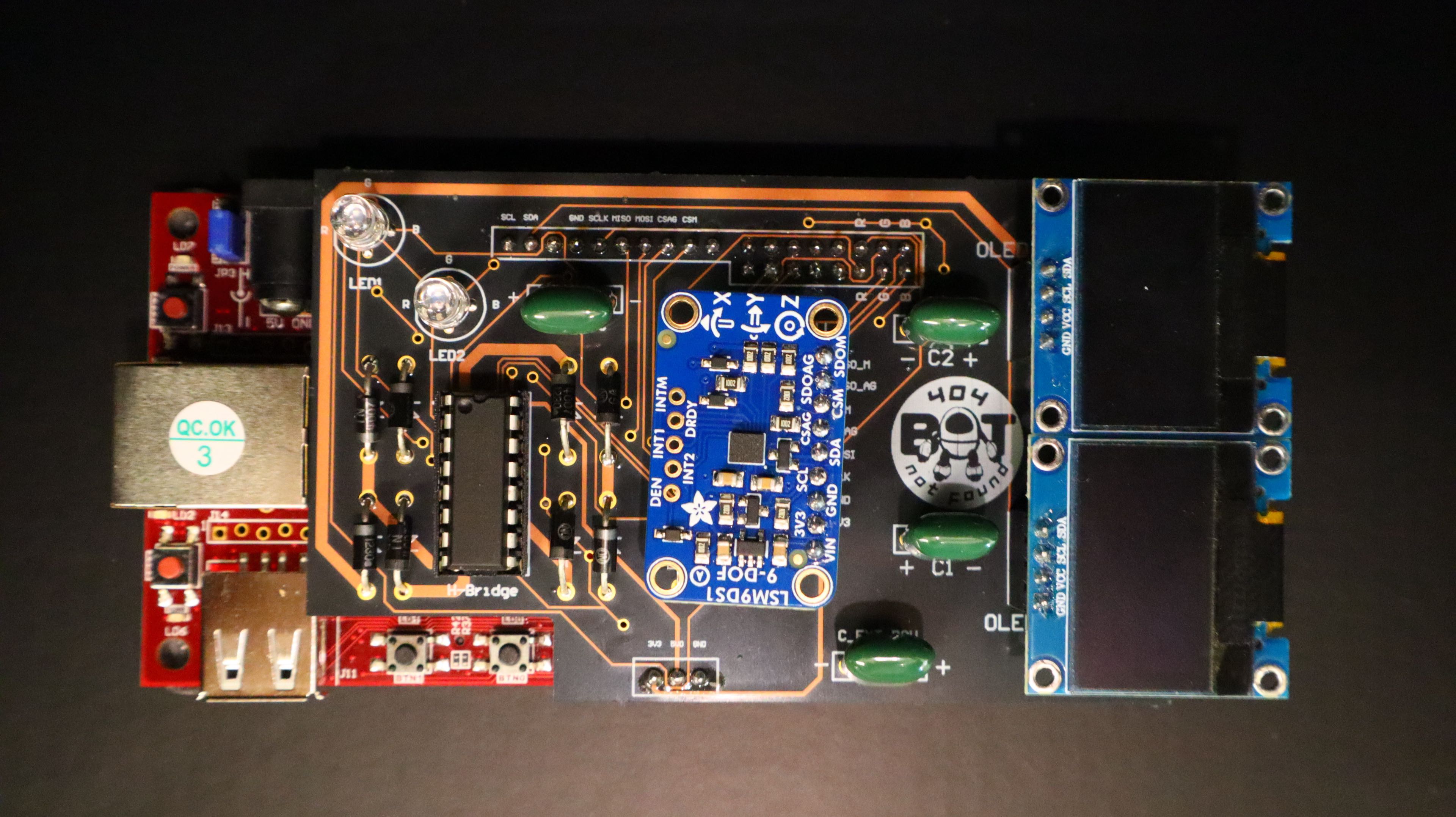
A custom board connecting sensors, displays, LEDs, motor-control hardware, and external interfaces to the Cora Z7.
Test procedures, operating instructions, block diagrams, address maps, and supporting material for future students.
My Contribution
I served as the project manager while also owning the master FPGA hardware-platform integration and deployment workflow. My technical responsibility was to maintain the Vivado design that brought the team’s peripheral subsystems together into a deployable Zynq-7000 configuration.
As subsystem requirements evolved, I incorporated the necessary AXI IP blocks, validated connections and address assignments, ran synthesis and implementation, generated the FPGA bitstream, and exported the XSA hardware platform used by the embedded-software team.
I maintained and distributed matching hardware releases so the bitstream, block design, XSA platform, testbench environment, and embedded applications remained aligned across project revisions.
I also assisted with the HDL verification effort by helping develop, execute, and debug AXI VIP simulations for the GPIO, PWM, SPI, and I2C peripherals. This work helped confirm register-level communication and peripheral behavior before physical deployment.
Deployment Workflow
Incorporate the required GPIO, SPI, I2C, PWM, reset, processing-system, and AXI interconnect blocks into the master Vivado design.
Check block connections, clocking, resets, address assignments, interfaces, and design-rule requirements before implementation.
Run synthesis and implementation, resolve design issues, and generate the FPGA bitstream for the Cora Z7.
Export the XSA hardware platform, distribute the matching release files, and support validation by the software and testbench teams.
Verification and Validation
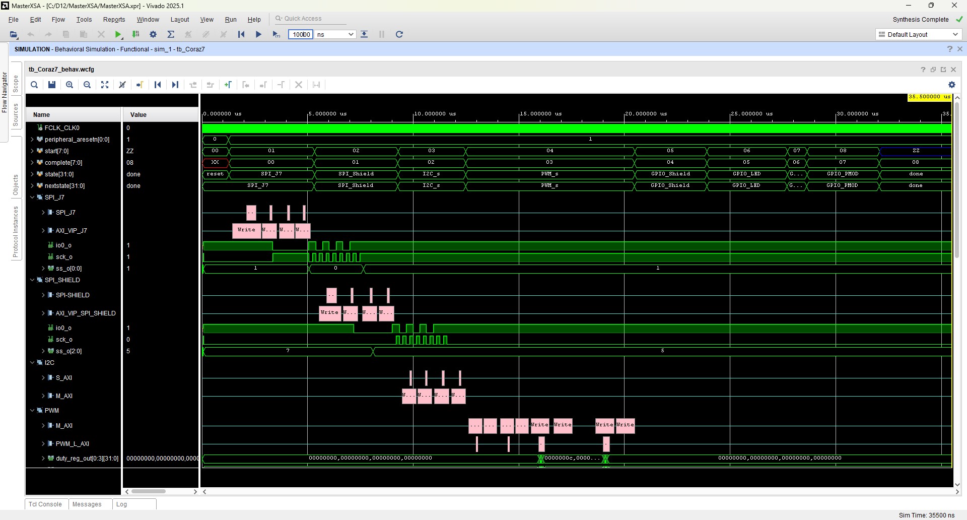
Verification was performed at multiple levels. Individual peripherals were first exercised through simulation and register transactions before being validated through embedded software and physical hardware.
The testbench environment instantiated the Cora Z7 design wrapper and used AXI Verification IP as the master interface. AXI VIP generated register transactions through AXI SmartConnect to exercise the memory-mapped GPIO, SPI, I2C, and PWM peripherals.
Hardware validation confirmed address mapping, register behavior, signal routing, and communication with external devices. Oscilloscopes and logic analyzers were used to inspect signals and troubleshoot timing, interface, and integration problems.
Performance Testing
I generated and tested multiple hardware-platform revisions using different programmable-logic fabric-clock frequencies. Peripheral operation and simulation were evaluated at 25, 100, 150, 200, and 250 MHz.
The platform’s communication interfaces operated successfully at 25, 100, and 150 MHz. At 200 and 250 MHz, SPI communication failed while I2C and the other interfaces continued to operate. The results identified a practical limitation involving the fabric clock, SPI divider configuration, and connected peripheral requirements.
Independent Project Extension
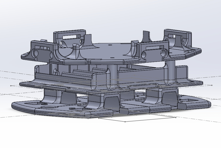
Outside the core team deliverables, I continued developing the platform as an autonomous robot. This extension demonstrated how the same HDL, peripheral, verification, and hardware-integration concepts could be applied to a complete physical system.
I designed the robot chassis and mechanical assembly in SolidWorks. The three-level structure organized the motors, batteries, sensors, Cora Z7, and project electronics while protecting the hardware and maintaining access for testing and development.
The lower level supported the drive system and boundary sensors, the middle level housed the batteries, and the upper level supported the FPGA board, electronics, and ranging sensors.
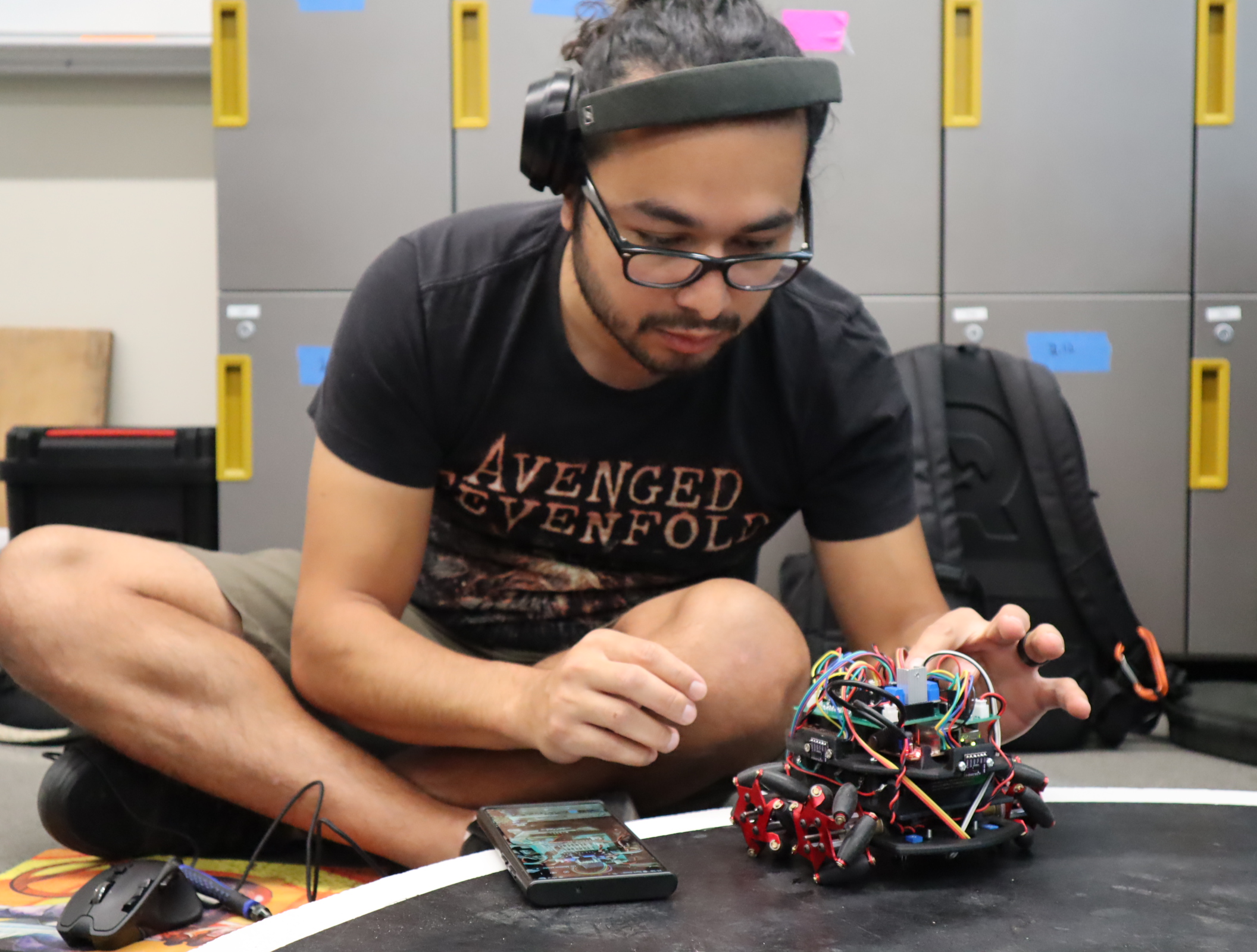
A three-level robot chassis was modeled in SolidWorks around the motors, sensors, batteries, Cora Z7, and project electronics.
Infrared sensors detected operating-area boundaries and could override movement commands to prevent the robot from leaving its intended area.
Time-of-flight ranging sensors supplied directional distance information for autonomous search and movement decisions.
FPGA-generated PWM and H-bridge control signals managed motor direction, speed, stopping, and corrective movement.
Engineering Challenges
The master FPGA platform required repeated updates as peripheral, software, testbench, and PCB requirements evolved.
Bitstreams, XSA platforms, address maps, simulation wrappers, and embedded applications had to remain synchronized.
The team needed to verify the individual IP blocks, AXI transactions, embedded control, external peripherals, and complete system behavior.
The system needed to demonstrate realistic engineering concepts while remaining understandable and reproducible for students.
Results
The project produced a working Zynq-7000 hardware platform with AXI-connected GPIO, SPI, I2C, and PWM peripherals, embedded applications, simulation testbenches, a custom PCB, and documented operating and testing procedures.
The platform demonstrated a repeatable workflow from HDL and IP integration through simulation, bitstream generation, XSA export, embedded-software integration, and physical hardware validation.
The autonomous-robot extension provided a path for applying the educational platform to sensing, motor control, safety logic, mechanical design, and real-time physical behavior.
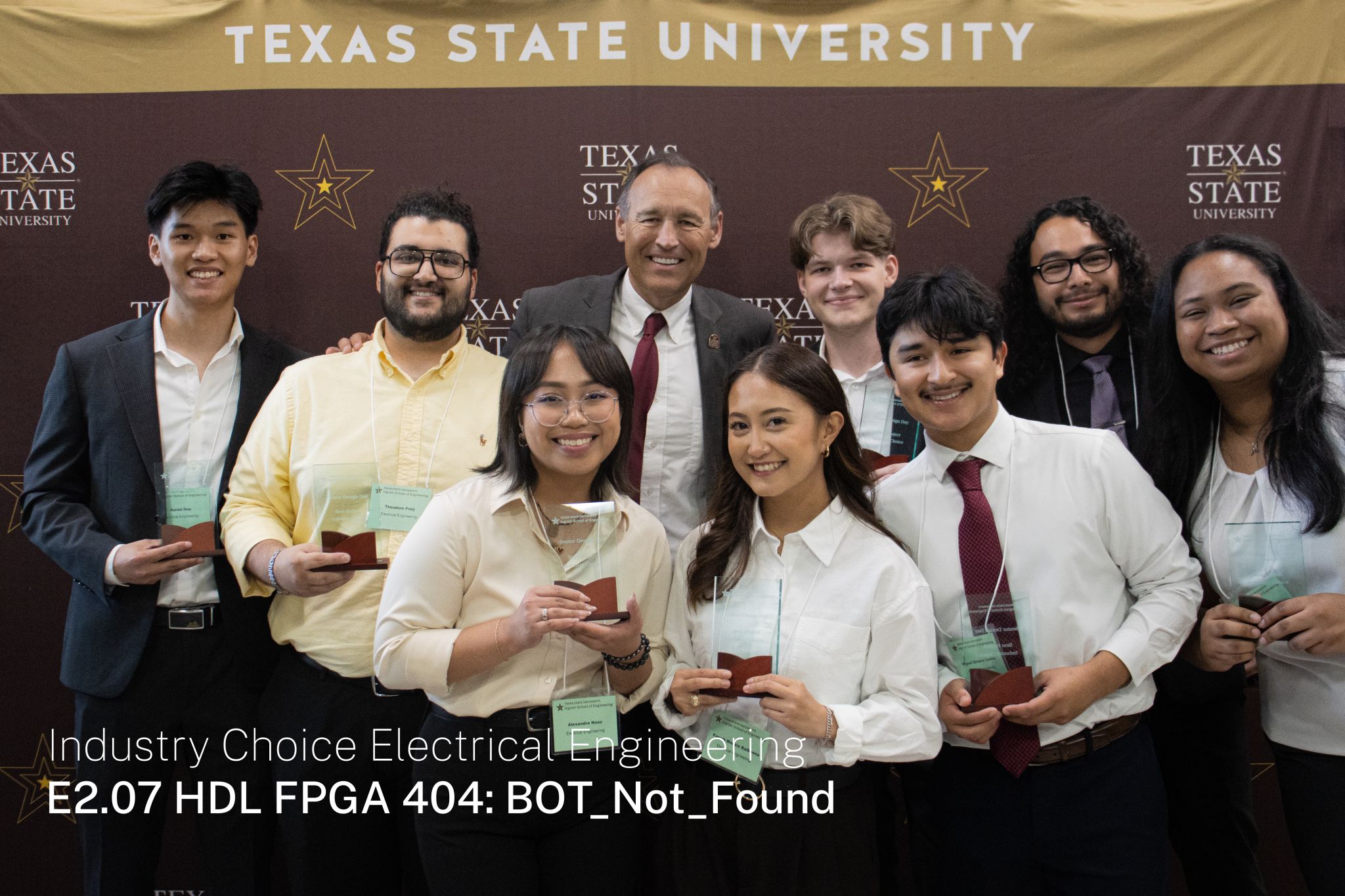
The project was recognized by visiting industry professionals as the top capstone project presented at the senior design showcase.
Project Gallery
Project Resources